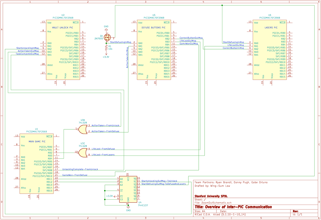
L.A.S.E.R. consists of four individual PICs, with lines for the individual PICs to post events to other PICs. The Main Game PIC manages the flow of the game between stages, the Vault Dial PIC manages the unlocking stage, the Defuse Buttons PIC manages the button pressing portion of the defusing stage, and the Lasers PIC manages the lasers portion of the defusing stage.
See the specifics for each individual PIC's circuit in the sections below:
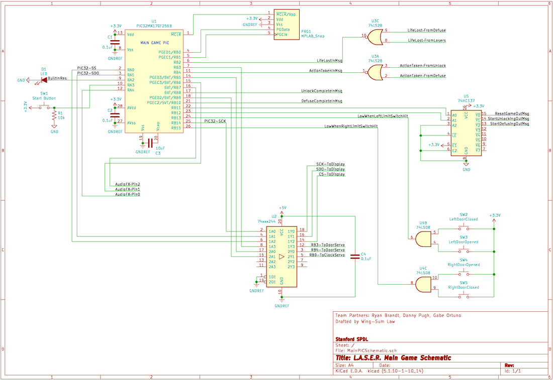
The "Main Game" module consists of its own PIC. This PIC has the following digital inputs and outputs:
Input from the yellow arcade start button
Output to the LED attached to the yellow arcade start button
Outputs for controlling the AudioFX board
Inputs through an OR gate from the Button Module, Laser Module, and the Unlocking Module that indicate that the user has taken any action
Inputs through an OR gate from the Button Module and the Laser Module that signal a life has been lost
Output to the Unlocking Module to indicate that the unlocking step has begun, and an input from the Unlocking Module that indicates when the user is done unlocking the vault
Outputs to the Button and Laser Modules to indicate that the defusing step has begun, and an input from the Button Module that indicates when the user is done defusing and has won the game
An output to indicate to all modules to reset themselves
Outputs for the servo motors and the SPI lines to the LED bitmap display
Note that the output signals for signaling the defusing step has begun and to reset the game are all active-low. These signals are controlled by two pins from the PIC through a 74HC137 decoder, to make up for the lack of total i/o pins on the PIC.
All of the outputs for the servos and the LED bitmap display need to be at 5 V, so they were all routed through the level shifting buffer chip, the 74HCT244. SPI lines for controlling the LED bitmap display come from the PIC, through the 74HCT244, and out to the LED bitmap display to control the number of lives remaining display. The servo lines go from the 74HCT244 to the servo that controls the timer and the two servos that control the vault doors.
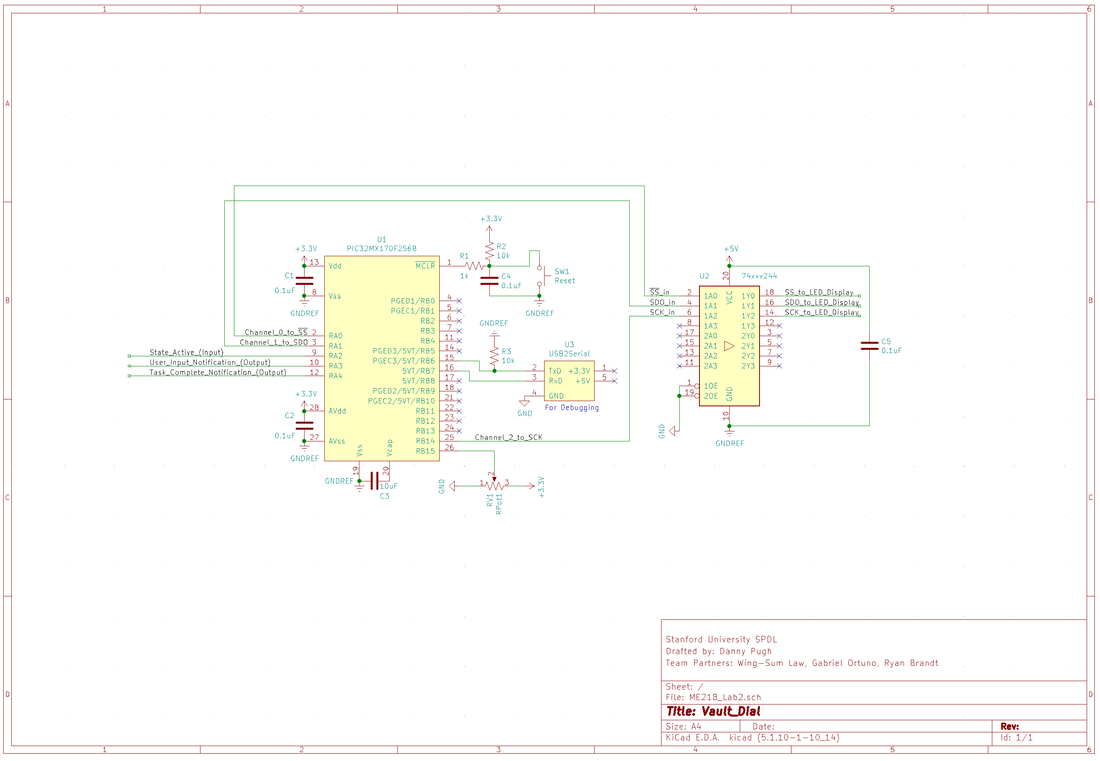
Electrical Design of Vault Dial Module
The Vault Unlocking Module consists of a single PIC with an analog input, a digital input, two digital outputs and an SPI protocol output consisting of a clock (CLK), digital output (DO) and an active low chip select line (SS). The analog input is used to collect position data from the potentiometer connected to the dial. The digital input is used for active high signals from the Main Game PIC. The digital outputs are used to communicate task completion and user input to the Main Game PIC. The MAX7219 based LED matrix display is connected to the PIC via a buffer line driver (74ACT244), which can convert a 3.3v input signal to 5v output signal. This is necessary since the PIC operates at 3.3v and the LED matrix operates at 5v. An Additional input and output are implemented for serial communication to aid in debugging during development.
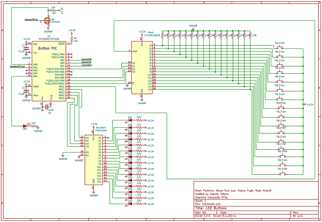
Electrical Design of the Button Module
The button module consists of its own PIC as well. This PIC has the following digital inputs and outputs:
Input from the "Main Game" PIC for inactive/active communication (MasterPICIn)
Output to the "Main Game" PIC for signaling user interaction (MasterPICOut)
Output to the "Main Game" PIC for signaling incorrect button being pressed (LivesOut)
Output to the "Main Game" PIC for signaling game won if all sixteen buttons are pressed within the allotted time (GameWon)
Output to the Laser Module for signaling a correct button was pressed so change laser configuration
Output select lines for controlling the LEDs through decoder
Output for controlling LED0
Output select lines for button presses through sixteen multiplexer
Input for common line from button press multiplexer
The button module PIC maps its input pins through a sixteen channel multiplexer (MUX), allowing four pins on the PIC to be used in determining the state of any of the sixteen buttons through reading a common output pin of the MUX. This PIC also maps its LED output pins to a four to sixteen decoder, allowing four pins on the PIC to light up sixteen different LEDs. To turn on an LED, the decoder sends a 3.3V low digital signal out to the normally high output LED we desire to light up per the four input lines from PIC. A nuance with this setup is that a low input across all four decoder input pins would map to lighting up the first LED by default. Since the team desired to have the possibility of having all LEDs off at once, as well as only have one LED lit at a time, the first output pin of the decoder is unused and instead LED0 is controlled through a direct output pin on the button module PIC. LED0 is also treated as a normally low output, opposite that of the decoder, hence the difference in wiring.
It should be noted that a small-signal MOSFET inverter was included for the "Main Game" PIC input to keep the signal consistent with the driving signals for all of the other modules. Instead of having the inverter, reprogramming the PIC in the future to interpret the signals differently would be best to reduce part cost, wiring complexity, margin of error, etc. The complete final schematic for the button module is shown in the image below:
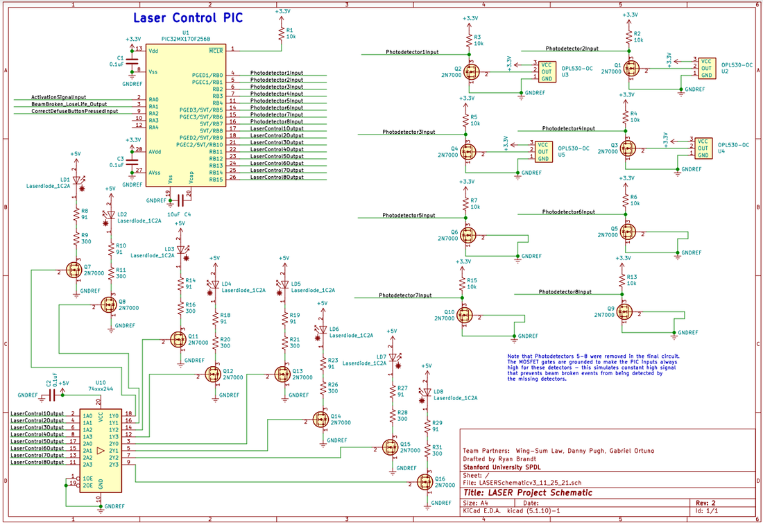
Electrical Design of the Laser Module
The laser module consists of its own PIC, and has the following digital inputs and outputs:
Input from the "Main Game" PIC for inactive/active communication (ActivationSignalInput)
Input from the "Button" PIC for communicating when a correct defuse button is pressed (CorrectDefuseButtonPressedInput)
Output to the "Main Game" PIC for signaling a beam broken / loss of life event (BeamBroken_LoseLife_Output)
Eight outputs for controlling the state of the eight lasers (LaserControlxOutput)
Eight inputs for reading the state of the (four, reduced from the original eight) photodetectors (PhotodetectorxInput)
To turn on a laser, the PIC sends a 3.3V high digital signal out to the level shifting buffer chip, the 74HCT244, to produce a 5V logic signal to switch a small-signal 2N7000 MOSFET that turns on a laser diode. A current limiting resistor limits the intensity of the laser diode's emitted light to an eye-safe level. A corresponding photodetector, placed in the beam's path, has an open collector output but includes an internal pullup to 3.3V. The detector pulls its output to ground in the presence of incident light surpassing an internal threshold value, so the detector has a low output voltage when the laser is on. A simple small-signal MOSFET inverter allows the PIC to see a logic high when the laser is on and the beam is unobstructed.
In this final iteration of the circuit, four photodetectors were removed. To make the wiring change reversible, the corresponding MOSFETs for the detectors were left in, though this is wasteful.
The complete final schematic for the laser module is shown in the image below:
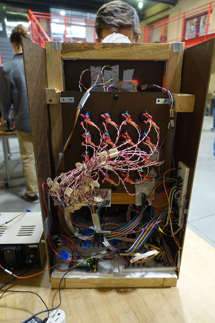
A Note on Wiring:
Having sixteen buttons (each with four electrical connections - two for switch contacts and two for LED terminals), eight lasers, and four photodetectors resulted in a lot of wires running around for the laser and button modules. Overall, the button module used about 60 feet of wire, while the laser module used about 20 feet. Cable management principles were used to manage all of this wiring. We labeled each wire, bundled related wires together, used a few cable ties, and hot glued breadboard connections to provide strain relief. An image of the back of the game captures these efforts quite well: